
XTC Can-Am X3 Turn Signal Kit Installation

XTC Can-Am X3 Turn Signal Kit Installation

In UTV Wiring Solutions, XTC Power Products leads the way. The TSS-Turn Signal System(Patent Pending) comes from its Plug & Play Product line.The machine comes with a marine switch that activates the turn signal mechanism and a blinking arrow that signals it. With no wires to be cut and no crimping, installation is simple. The device comes with pre-made wire harnesses that interface with the OEM harness, unplug the backlight harness connector of the car, and plug-in our harness, it's that easy. The brake lights operate much like a car turn signals, including Hazard LightsSince these vehicles are primarily used for off-road use, the lit dash switch is more practical than the bulky turning levers which break off. It includes a lit Hazard Switch and rear power out to light or whip light on the license plate.
Remove the Kick Panels

Remove the kick panel on the driver side by removing the two Torx screws. The fender can be removed if desired but not necessary.
Mount the Control Module
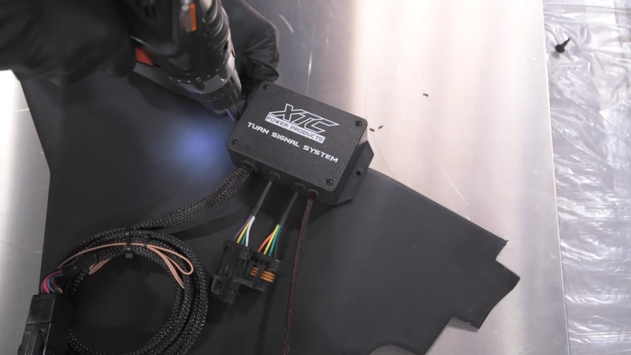
Pull a 1⁄4 "hole at the Kick Panel to the right of the top center. Using the supplied Screw and Locking Nut attache the control module to the inside of the kick panel.
Run the Rear Harnesses

Start from the rear driver’s side light harness. These connections are in the front engine area on the plastic wall. Take the cable end with two connectors on it and run it from the Driver's side of the OEM Rear Light Harness to the Passenger side of the OEM Rear Light Harness. Follow the wiring of the factory, unplug both harness and install the XTC harness. Secure using the provided cable ties.

Push through the front kick panel the other end of the rear harness. The plastic on the MAX has a perforated circle behind the driver's seat or rear seat. You can move the single connector from the rear harness to the passenger compartment through the plastic gap. Follow the frame along the driver's side. The harness can be concealed in the side panels, and is placed behind the removed kick panel and plugged into the Control Module mating connector.

Install Activation Switches

Attach the Harness switch to the Control Module. Remove one of the switch blanks and pass through the opening of XTC 10-pin switch connector, grease the terminals with the supplied grease and add it to XTC switch and insert the switch into the opening.
Install Horn

Using the provided hardware, install the horn bracket onto the horn. Remove the bolt from the T brake line mount in the firewall next to the rubber grommet, and mount Horn Bracket under it and reinstall the bolt. Attach Black and Violet wire from the front harness to the horn terminals
Run Power Wire

Remove the Center plastic cover under the dash exposing the main wire harness. To make it easier to use, remove the cable tie that holds the AUX Plug. The connector may be concealed in the back of the harness. By pressing the middle button, unplug the OEM connector port cover (White Plug). Connect the 2-way power cable to the control module and conduct the power wire to the AUX cable and connect it to the port.


 With the Shock Therapy STS Tune")


